Add Zigbee Green Power (ZGP) devices
Zigbee Green Power (ZGP) is a technology that enables ultra-low power devices like switches and sensors to operate within Zigbee networks. ZGP devices are designed to be energy-efficient by only transmitting messages during normal operation.
Add ZGP switches
It is recommended to first add lights to all the groups within a wireless network before adding ZGP switches. Unassigned lights nearby create more BLE traffic, which can cause localizing ZGP devices to take longer. Remember, at least one light must be added to a group or zone before any ZGP devices can be added.
| ZGP devices must be localized and installed within direct Zigbee range of the groups they will control. |
-
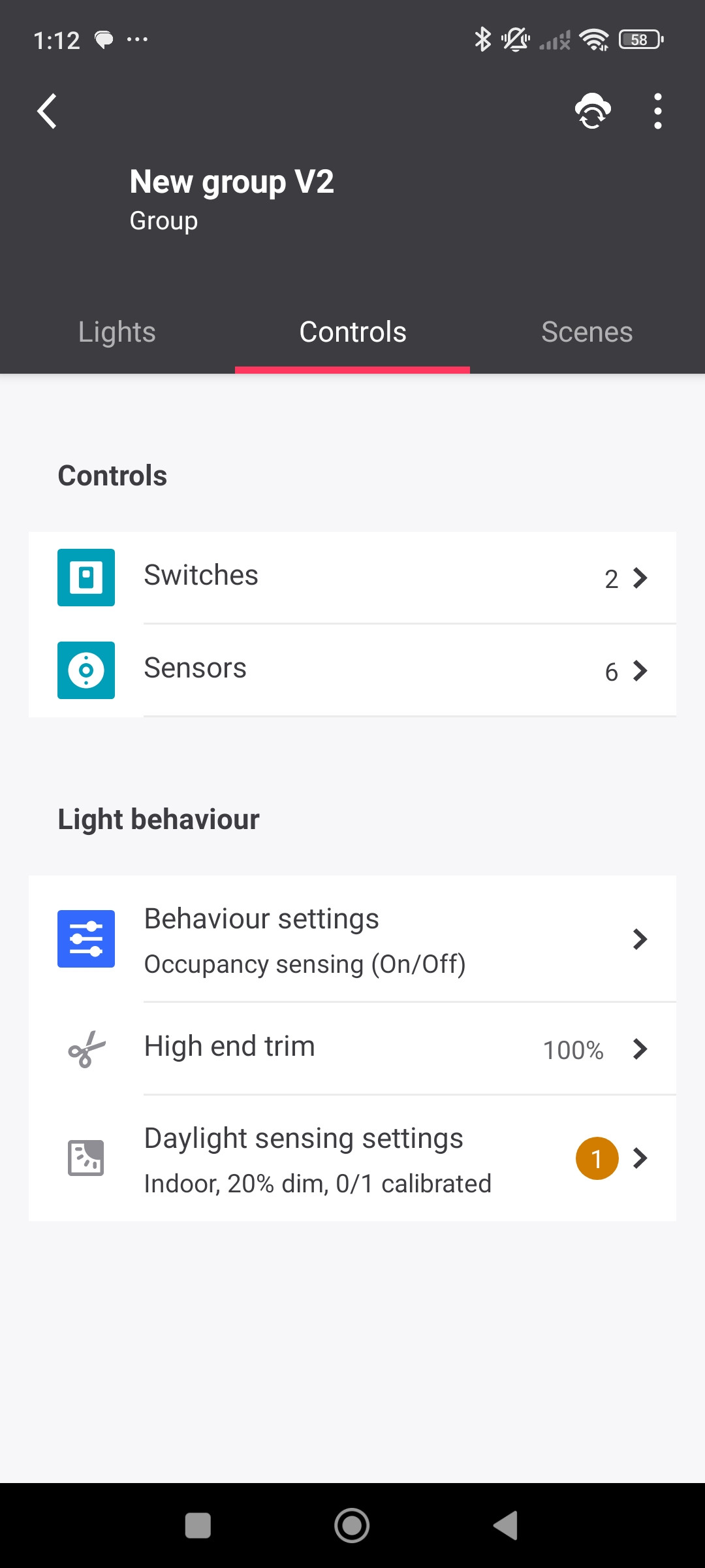
Navigate to the appropriate Group, then tap Controls.
-
Tap Switches.
-
Tap Add switch.
-
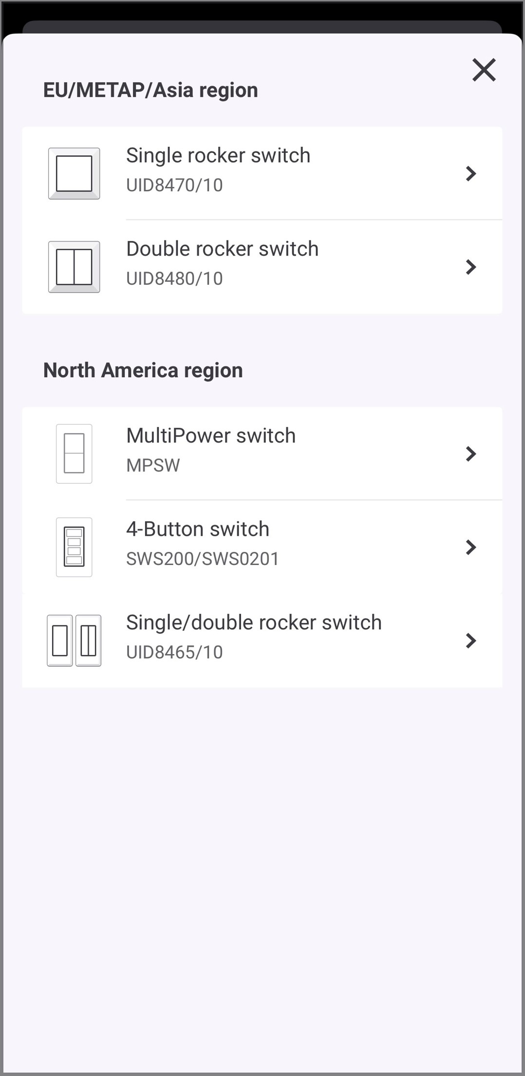
Tap the appropriate switch from the list based on the model of switch installed on-site.
-
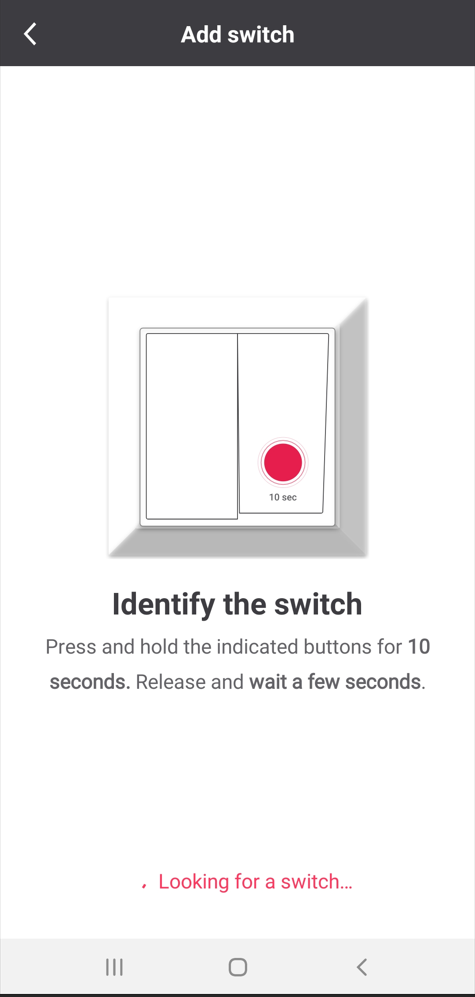
Follow the add switch process prompted by the app. The commissioning steps differ for each available ZGP switch type, so read and complete each on-screen instruction carefully to successfully add the switch.
-
To configure a single/dual rocker switch and 4-button switch:
-
Once the switch is joined, type a name for the switch, then tap Done. If you are adding a convertible single/dual rocker switch, a screen will appear for you to select the rocker configuration you desire.
-
For any 4-button or dual rocker switch joined, the Configure switch now? screen will appear. If you tap Later, then you will need to edit the switch configuration later if you wish to add scenes to your switch buttons. Single rocker switches cannot be configured further.
-
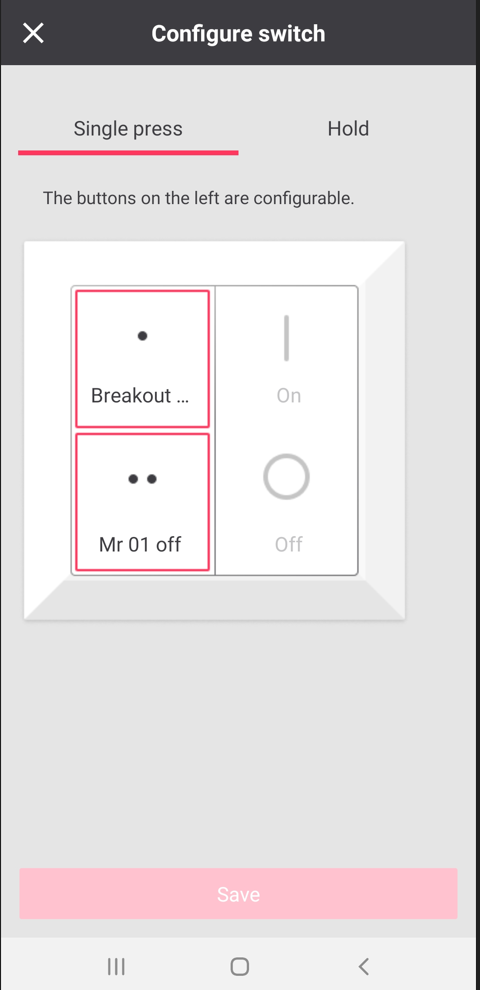
For any 4-button or dual rocker switch joined, if you tap Configure on the Configure switch now? screen, the Configure switch screen appears. Tap on each highlighted button to select the desired scene to assign to each switch button.
-
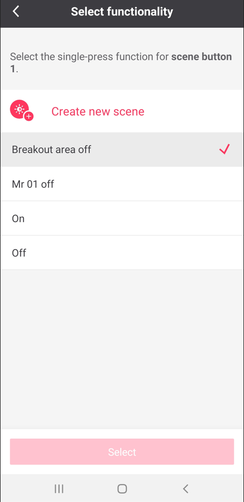
When either button is tapped to add a scene, the Select functionality screen appears. If scenes have already been created, you can select them from the list. Alternatively, tap Create new scene to configure a new scene to assign to the switch button (Refer to Create Scenes for more details).
-
Tap Save to record the changes.
-
Once the switch is joined, If you do not assign scenes to your switch now, or you wish to change the configuration later, just navigate back to the Controls, then Switches screen in the group.
-
For the switch you wish to configure, tap the 3-dot-ellipsis beside the switch, then tap Change configuration. This will open the Configure switch screen where you can assign, change or remove scenes from switch buttons.
-
-
MultiPower switch (MPSW):
Prerequisites
Before configuring a MultiPower Switch:
-
The MultiPower Switch must be successfully added to the wireless network.
-
At least one light must be assigned to the group before adding and configuring the switch.
-
Existing user-defined scenes are available for assignment to configurable switch buttons. If no suitable scene is available, create a new scene during switch configuration.
-
Color tuning functions are supported only when the controlled luminaires support adjustable color temperature.
To configure a MultiPower switch:
-
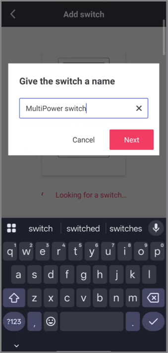
Once the switch is recongonized, type the name of the switch in the Give the switch a name field, and then tap Next.
-
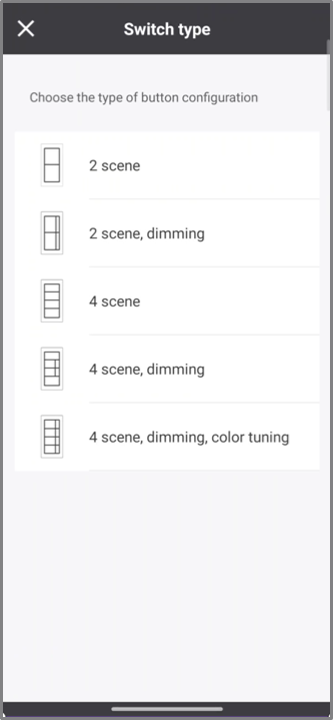
In the Switch type screen, select the button pad configuration that matches the physical switch.
The MPSW supports interchangeable button pad options for scene control, dimming, and color tuning. Available configurations include: 2 Scene; 2 Scene, Dimming; 4 Scene; 4 Scene, Dimming; and 4 Scene, Dimming, Color Tuning.
Color tuning functionality is available only when the controlled luminaires support adjustable color temperature. If color tuning is not supported, the Warmer and Cooler actions will not affect the luminaires. Result: A Switch added successfully message appears, and the Assign scenes screen displays the selected button pad configuration and its default out-of-box (OOB) button assignments.
-
In the Assign scenes screen, select a configurable button (indicated by the '>' arrow) if you want to modify its actions.
Buttons without the '>' arrow are predefined and cannot be configured. 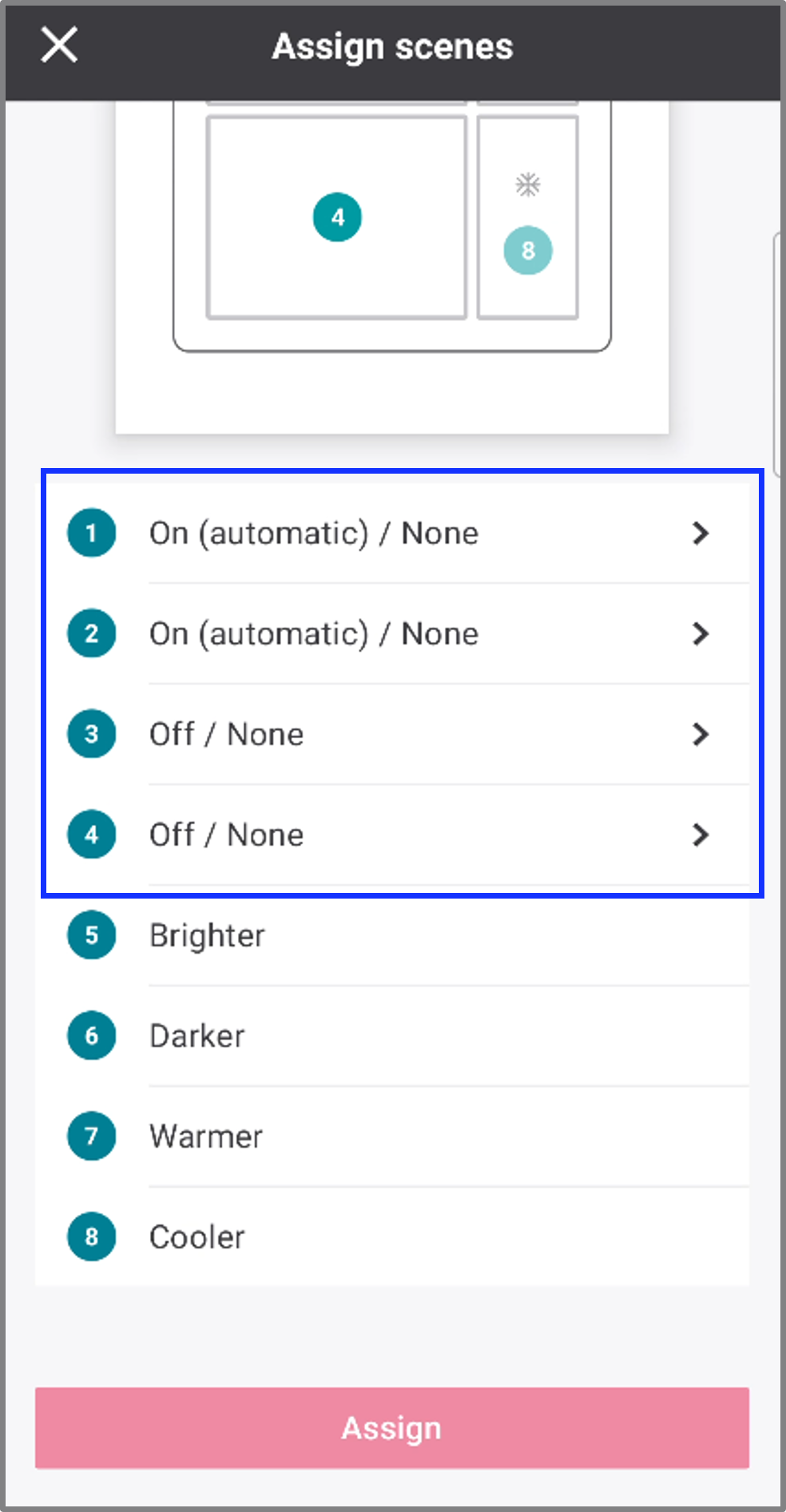
-
Configure the button actions. Select Single press or Hold, and then assign the desired action.
Available Single press actions include None, On, Off, and user-defined scenes.
User-defined scenes created previously are available for selection. If no scenes are available, click Add Scene to create a new scene. To create or manage scenes, see Create scenes. 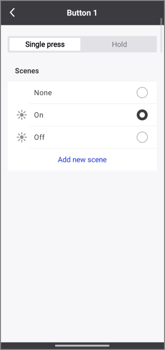
Available Hold actions include None, Brighter, Darker, Warmer and Cooler.
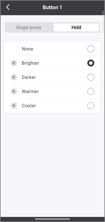
Hold action behavior
Hold action Behaviour Brighter
Press and hold the button to gradually increase light output. Release the button to stop dimming.
Darker
Press and hold the button to gradually decrease light output. Release the button to stop dimming.
Warmer
Press and hold the button to gradually reduce the color temperature, producing warmer light tones.
Cooler
Press and hold the button to gradually increase the color temperature, producing cooler light tones.
-
Available button actions depend on the selected button pad configuration and the capabilities of the controlled luminaires.
-
All MPSW switches within a group share the same button pad configuration and button assignments. Additional MPSW switches added to the group inherit the configuration of the initially assigned switch. Individual MPSW switches cannot be configured independently.
-
-
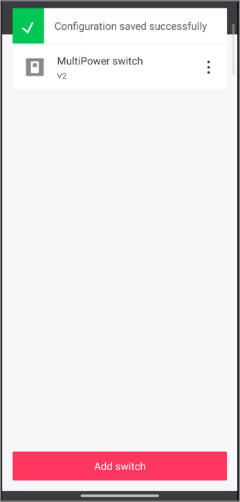
Repeat for additional buttons as required, and then tap Assign.
Result: The application displays a Configuration saved successfully message. The selected button pad configuration and button assignments are applied.
-
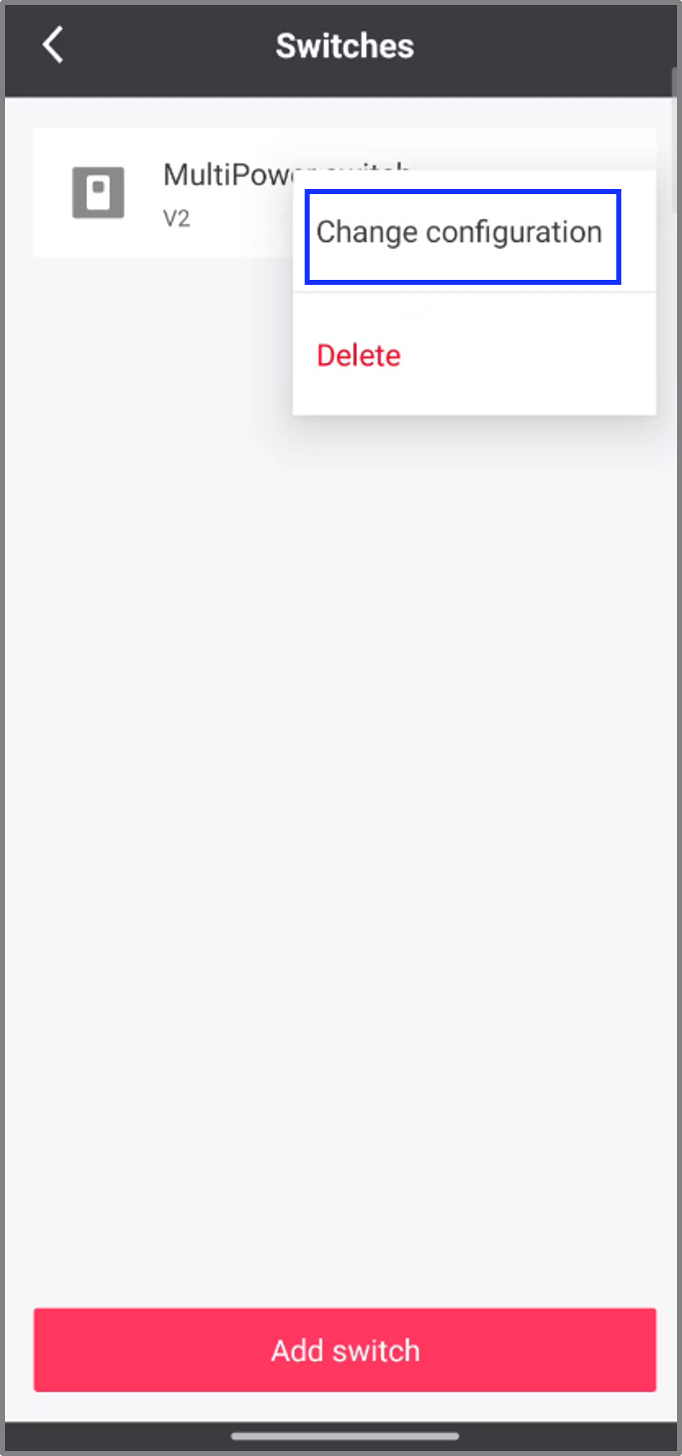
Once the switch is added, if you want to further change the configuration, navigate back to the Controls, then Switches screen in the group.
-
For the switch you wish to configure, tap the 3-dot-ellipsis beside the switch, then tap Change configuration. This will open the Assign scenes screen where you can assign, change or remove scenes from switch buttons.
-
-
Add ZGP sensors
It is recommended to first add lights to all the groups within a wireless network before adding ZGP sensors. Unassigned lights nearby create more BLE traffic, which can cause localizing ZGP devices to take longer. Remember, at least one light must be added to a group or zone before any ZGP devices can be added.
| ZGP devices must be localized and installed within direct Zigbee range of the groups they will control. |
There are two types of battery-powered ZGP sensors:
-
ZGP Occupancy sensor:
-
These sensors are used for occupancy sensing only and can detect both major and minor movements.
-
Occupancy sensors do not have the capability for daylight sensing.
-
-
ZGP Multi-sensor:
-
A multi-sensor has occupancy sensing like the occupancy sensor, but also includes light level detection for daylight sensing, which means it can adjust the lighting level based on the amount of ambient daylight present.
-
Multi-sensors cannot be combined in groups with luminaires with built-in sensors, as the built-in sensors ignore both occupancy and daylight sensing messages from multi-sensors. They can only be combined with luminaires and devices without built-in sensors, such as luminaires with built-in transceivers or wireless drivers, as well as Smart T-LEDs and switch relays.
-
Multi-sensors must be added to zones (sub-groups), as this is where daylight sensing functionality is accomplished. Only one multi-sensor is allowed per zone, to prevent multiple multi-sensors from sending conflicting daylight sensing messages to the same lights within a zone.
-
Add occupancy sensors
-
Navigate to the appropriate Group, then tap Controls.
-
Tap Sensors.
-
On the Sensors screen, tap Add sensor.
-
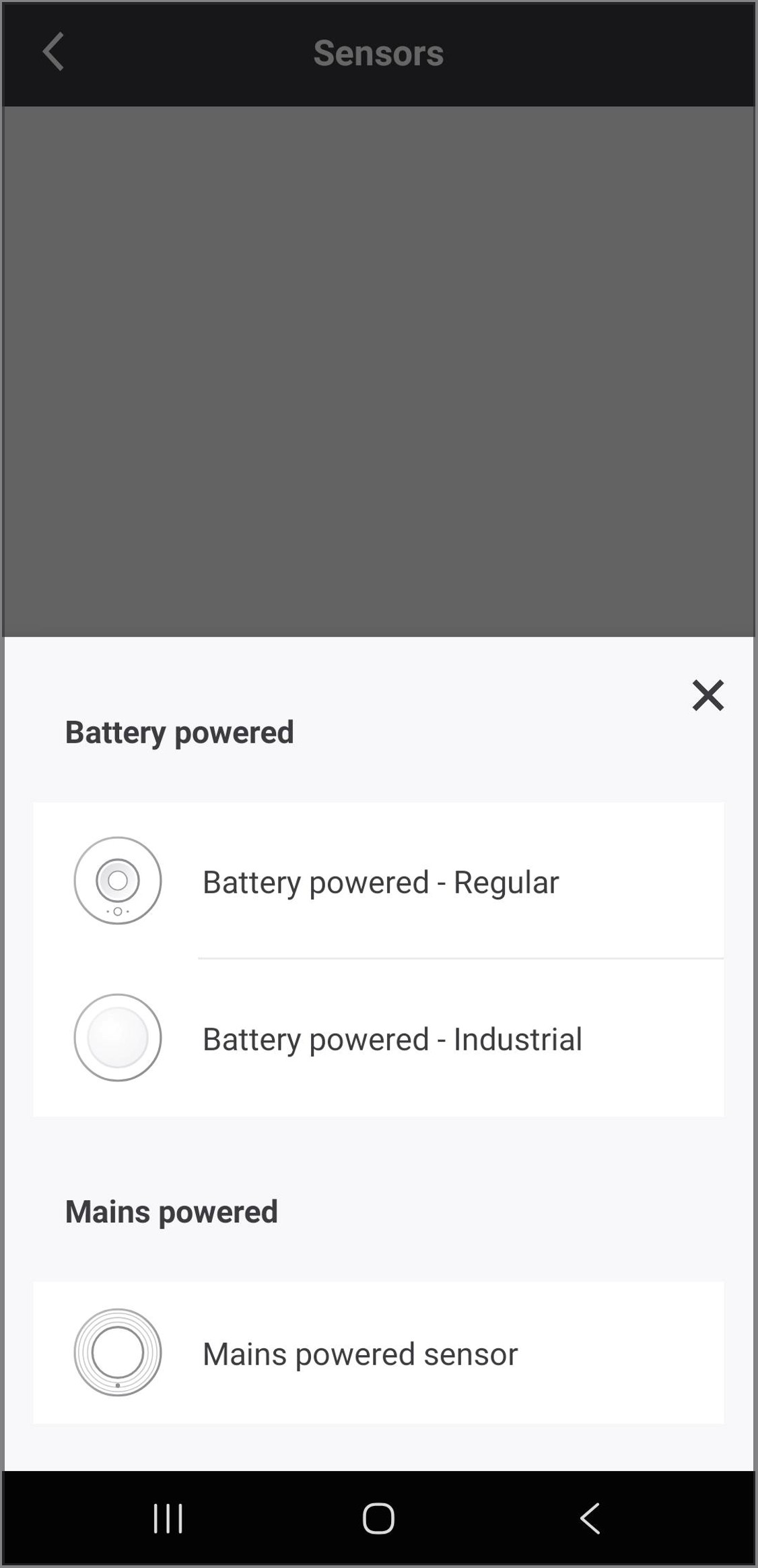
Tap the appropriate sensor from the list based on the model of sensor installed on-site.
-
Follow the add sensor process prompted by the app. Be aware that sensors have different workflows depending on if they regular or industrial sensors. Read each screen and follow the instructions carefully, as all steps must be completed properly to successfully add the sensor.
-
Note that the green LED indicator on the sensor will blink slowly when the commissioning button is pressed (or when the battery strip is first pulled out), then will blink twice quickly when the sensor successfully joins. If the LED indicator blinks red, reset the sensor by pressing and holding the reset button for approximately 8 seconds (you should see both the red and green indicator LEDs on the sensor blink twice), then retry the process.
-
Once the sensor is joined, type a name for the sensor, then tap Done.
-
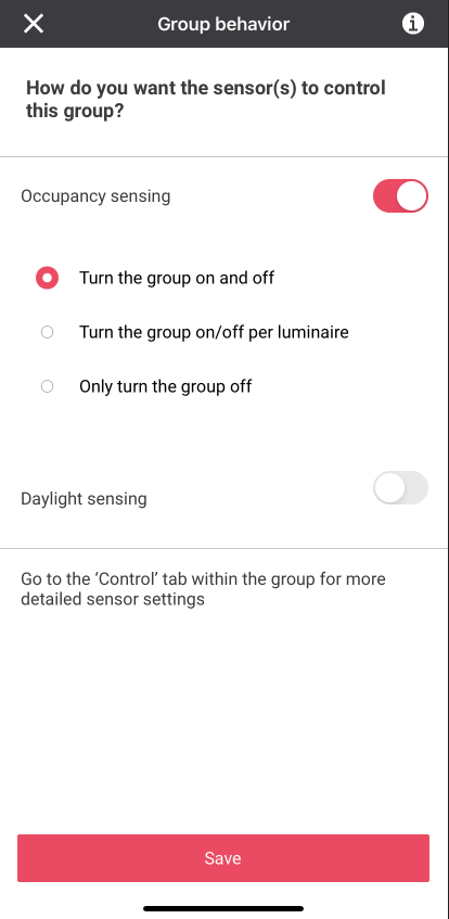
The Group Behavior screen appears. On this screen, you can set the group behavior using the options presented. However, this is optional and you may wish to set the group behavior later when you can also modify the behavior parameters. If you wish to set the group behavior later (recommended), or you had already set the group’s behavior previously, then tap on the X symbol to close this screen, or else your parameter settings will be overwritten by default values.
Add multi-sensor
A multi-sensor enables daylight regulation for lights in a zone without built-in sensors. A maximum of one multi-sensor can be added per zone in the group. Other occupancy-only sensors can be added at the group level if needed..
-
Navigate to the appropriate Group, then tap Controls.
-
Tap Sensors.
-
On the Sensors screen, tap Add sensor.
-
Tap the appropriate sensor from the list based on the model of sensor installed on-site.
-
Follow the add sensor process prompted by the app. Be aware that sensors have different workflows depending on if they regular or industrial sensors. Read each screen and follow the instructions carefully, as all steps must be completed properly to successfully add the sensor.
-
Note that the green LED indicator on the sensor will blink slowly when the commissioning button is pressed (or when the battery strip is first pulled out), then will blink twice quickly when the sensor successfully joins. If the LED indicator blinks red, reset the sensor by pressing and holding the reset button for approximately 8 seconds (you should see both the red and green indicator LEDs on the sensor blink twice), then retry the process.
-
Once the sensor is joined, type a name for the sensor, then tap Done.
-
The Group Behavior screen appears. On this screen, you can set the group behavior using the options presented. However, this is optional and you may wish to set the group behavior later when you can also modify the behavior parameters. If you wish to set the group behavior later (recommended), or you had already set the group’s behavior previously, then tap on the X symbol to close this screen, or else your parameter settings will be overwritten by default values.
-
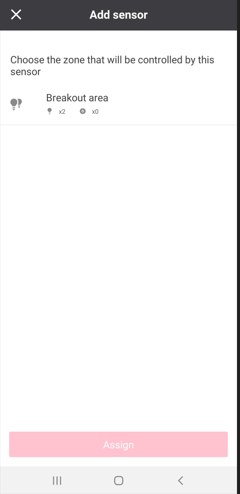
Select the appropriate zone from the list, then tap Assign.