Integrate a NatureConnect project with PRF/PRA
This topic details the steps required to integrate PRF/PRA with NatureConnect.
| Before integrating NatureConnect with PRF/PRA see how to design a NatureConnect project with PRF/PRA |
Install
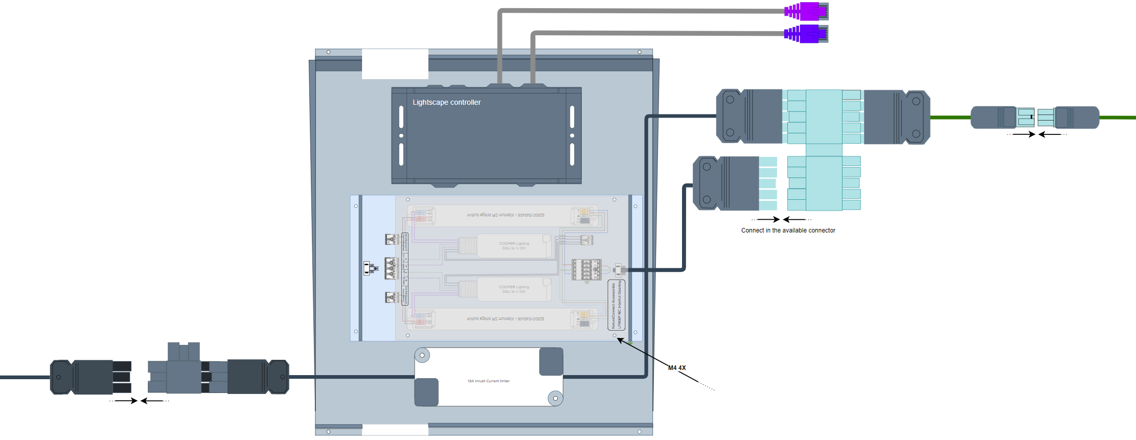
To install the NatureConnect devices, use the following steps:
Unpack the gear tray, sensors and switch
Ensure the following:
-
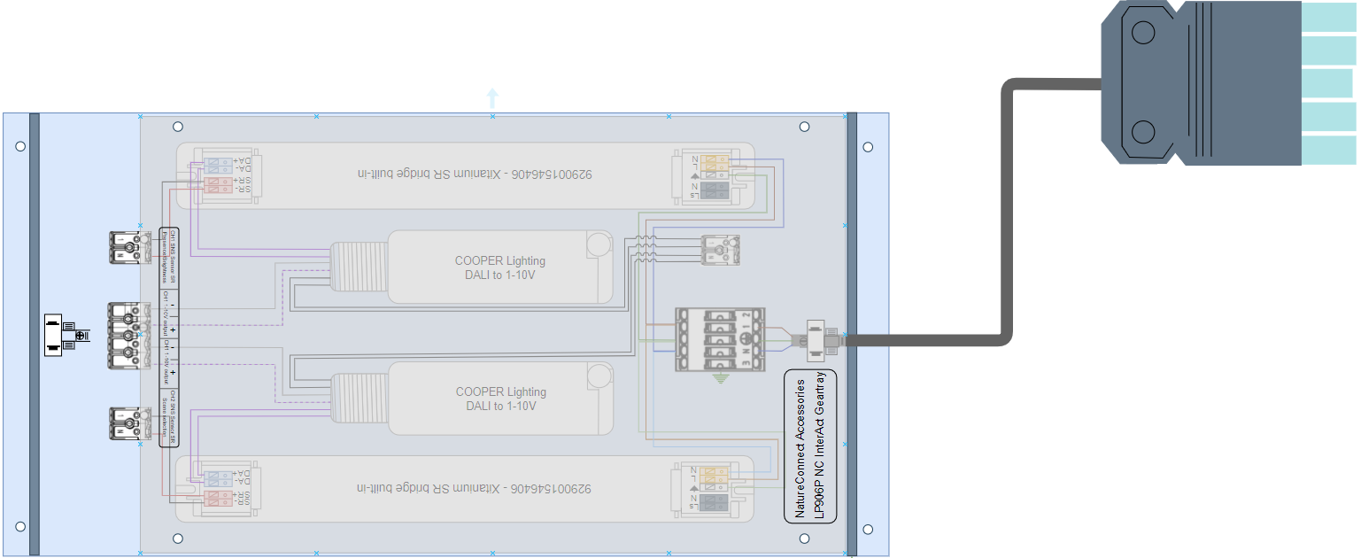
Wire for connection between Gear tray - Cabinet:
-
Input wire cross-section (solid conductor wire): 0.5 - 2.5 mm²
-
Input for wire ends with ferrule to the maximum diameter stated: max. ø 1.8mm
-
Input for tinned wire ends: max. ø 1.8 mm
-
-
Wire for connection between Gear tray and Sensors:
-
Input wire cross-section (solid conductor wire) 0.25 to 0.75mm2 / 24 to 18 AWG
-
Input wire cross-section (stranded wire) 0.3 to 0.5mm2 / 22 to 20 AWG
Input wire cross-section (solid conductor wire): 0.5mm2 The installation instructions for the sensor and switch can be found in their respective specification sheets.
-

Commission PRF/PRA with NatureConnect
Create two groups with the following specification:
| See how to add groups. |
-
Group name:
Group 1 - Presence -
Room Type:
Meeting room -
Group behavior:
Group Auto On Auto Off
-
Group name:
Group 2 - Scene selection -
Room Type:
Meeting room -
Group behavior:
Group Manual On Auto Off
| Each group has a different control scope. The first is aimed at sensing and controls light on/off/dimming light behavior, while the second is controlling the scenes via the light switch. |
Add sensors & switch
| To avoid EMI issues cables between sensors and gear tray should be maximum 3m long. |
Add the following to each group:
-
Fixture type -
SNS210 IA
-
Fixture type -
SNS210 IA -
Switch type:
UID8480/10 ZGP Dim 4B
Link groups to Wireless Gateway
-
Link the groups to the Wireless Gateway. This in turn links all sensors and switches to the Wireless Gateway
Add scenes
A scene is added only for Group 2 - Scene selection
|
Select the Group 2 - Scene selection and add the following scenes:
-
Scene name:
Day rhythm -
Light level (Zones):
90% -
Light level (Lights not in zone):
100%
-
Scene name:
Energize -
Light level (Zones):
57% -
Light level (Lights not in zone):
100%
-
Scene name:
Relax -
Light level (Zones):
43% -
Light level (Lights not in zone):
100%
-
Scene name:
Present -
Light level (Zones):
29% -
Light level (Lights not in zone):
100%
-
Scene name:
Off -
Light level (Zones):
10% -
Light level (Lights not in zone):
100%
Deploy all scenes and validate the project.